Piping Design and Drafting Demystified: A Beginner’s Guide
Piping systems form the circulatory network of many industrial plants — from oil & gas, petrochemical, power, water treatment, to HVAC and food processing. Behind the smooth flow of fluids lies a careful orchestration of design decisions, technical calculations, drafting precision, and real?world constraints. Yet for many beginners, “piping design” feels like magic — how do you decide where pipes go, what fittings to use, how to draw them, and how to tie design with fabrication?
This article titled “Piping Design and Drafting Demystified: A Beginner’s Guide” aims to unveil that magic. We’ll walk you through the core concepts, terminology, drawing practices, software tools, and step?by?step workflows. Throughout, we’ll show how Piping Design and Drafting Training can help you bridge from theory to hands?on skills, and help you position yourself in this high-value domain.
2. Why Piping Design & Drafting Matters
Before diving into definitions, let’s understand why mastering piping design and drafting is worthwhile:
- Critical in industries: Virtually every chemical, petrochemical, power, refinery, water, and processing plant demands intricate piping networks. A well-designed piping system reduces cost, avoids rework, eases maintenance, and ensures safety.
- High demand & specialization: Piping designers and drafters are niche professionals. Good skills lead to better job opportunities, consulting roles, or independent contracts.
- Bridges design and fabrication: You’re the link between engineers’ conceptual design and the hands that build. You translate process requirements into real world drawings.
- Error cost is high: A wrong routing, clash, misalignment, or incorrect support can lead to huge extra cost, plant shutdowns, or safety risks.
- Continuous evolution: Technologies like 3D CAD, AI in diagram generation, digital twins, and augmented reality are shaping the future. If you begin early, you ride the wave.
Therefore, investing time in Piping Design and Drafting Certification is a smart foundation. It accelerates your confidence, hands-on skills, and market readiness.
3. Fundamentals & Key Concepts
3.1 What Is Piping Design?
Piping design is the engineering discipline focused on planning how fluid lines (pipes) will connect various equipment in a system—ensuring correct flow, pressure, thermal expansion, alignment, space constraints, and code compliance. While “hydraulic design” (pressure drop, flow, sizing) is part of it, piping design broadly also deals with routing, supports, flexibility, and integration.
As one experienced forum contributor explained:
“The first thing to understand is that ‘piping design’ means different things to different people. Probably the most common use … is for the engineers and draftspeople who design and draw the physical layouts of piping.”
3.2 What Is Piping Drafting?
Piping drafting is the art (and technical work) of drawing the piping system—creating 2D or 3D drawings with correct representation, dimensioning, annotations, symbols, isometric views, and drawings that fabricators and installers can use. Drafting makes the design visible and actionable.
3.3 Differences between Design & Drafting
| Aspect | Piping Design | Piping Drafting |
| Focus | Engineering decisions: routing, pressure drop, supports, safety | Representation: drawings, symbols, views, dimensions |
| Input | Process flow, equipment spec, codes | Design output, CAD tools, standards |
| Output | Layout, specs, calculations | P&IDs, isometrics, shop drawings |
| Skillset | Engineering judgment, analysis | Drafting convention, CAD proficiency |
Design and drafting go hand in hand. A good designer must understand drafting constraints; a good drafter should recognize design intent and flag inconsistencies.
3.4 Typical Industries & Applications
- Oil & Gas and Petrochemical
- Power Plants / Thermal / Combined Cycle
- Chemical & Process Plants
- Water Treatment / Wastewater
- Pharma / Food / Beverage
- HVAC / Building Services (for smaller scale piping)
Within these, you may see process piping, utility piping (steam, cooling water), instrumentation piping, and special systems (e.g. gas, flare, fire water).
4. Core Components & Terminology
Before designing or drafting, you must know your building blocks. Here are essential components and terms.
4.1 Pipes, Fittings & Flanges
- Pipes: The straight runs that convey fluid; they have a nominal size (NPS, DN), material (e.g. carbon steel, stainless steel), schedule (wall thickness), and class.
- Fittings: Connectors like elbows, tees, reducers, bends, caps used to change direction, branch, or change diameter.
- Flanges: Bolted connections allowing sections to join or be dismantled. Types include weld neck, slip-on, blind, forged, etc.
4.2 Valves & Accessories
- Valves: Control flow—gate, globe, ball, butterfly, check valves, control valves, etc. Each has unique symbols and behavior.
- Accessories: Items such as strainers, steam traps, orifice plates, filters, silencers, instruments.
4.3 Instrumentation & Control Devices
Instrumentation devices (flow transmitters, pressure gauges, temperature sensors, control loops) require piping connectivity and location. On the P&ID, their symbols matter.
4.4 Supports, Expansion Joints & Anchors
- Supports & Hangers: Hold pipes; types include clamps, roller supports, U-bolts, spring hangers.
- Expansion Joints / Loops: Accommodate thermal expansion.
- Anchors / Guides: Control movement, direct expansion forces.
4.5 Nozzles, Tees, Reducers, Elbows
- Nozzles: Interface between equipment and piping.
- Tees / Lateral tees: Create branches.
- Reducers: Change diameter.
- Elbows / Bends: Change direction (often 45°, 90°).
Understanding each piece and when to use them is essential for logical routing and drawing clarity.
5. Design Codes, Standards & Best Practices
Standards and best practices are the backbone of safe and consistent piping design.
5.1 Pipe Design Codes (e.g. ASME B31.3)
ASME B31.3 (Process Piping) is one of the most widely used codes. It governs allowable stresses, design conditions, testing, inspection, and materials. Training courses often include teaching how to apply B31.3 in real designs.
5.2 Material Selection & Specifications
Selecting the right material (carbon steel, stainless, alloy, plastic, etc.) hinges on fluid type, temperature, pressure, corrosion, mechanical properties, and cost.
5.3 Pipe Class, Line Numbers & Spec Sheets
Every pipe line is assigned a Line Number and Class (defining flange, wall thickness, schedule) and documented in Line Specifications. A spec sheet outlines the material, insulation, corrosion allowance, fittings allowed.
5.4 Stress, Flexibility & Thermal Expansion
Pipes expand and contract with temperature changes. You must model the stress and flexibility to avoid over-stress or buckling. Supports, guides, anchors, and expansion loops are used to manage these forces.
5.5 Safety, Tolerances & Margins
Always include safety factors, tolerances, and margin allowances. Consider vibration, seismic loads, insulation expansion, creep, cyclic loads, etc.
6. Piping Layout & Routing Techniques
Routing is the heart of how piping travels in the plant environment.
6.1 Plot Plans & Site Layout
Start with the overall site or plot plan that shows equipment layout, roads, columns, structural supports. You must respect buildings, maintenance access, clearances.
6.2 Equipment Layout & Nozzle Orientation
Each equipment (pump, exchanger, vessel) has nozzles that must face certain directions to facilitate piping. In early layout, ensure nozzles don’t conflict physically.
6.3 Pipe Rack & Yard Piping
Pipe racks are structural frames to support multiple pipelines. Yard piping covers external interconnections. You must plan rack sizes, spacing, clearance, and vertical stacking.
6.4 Routing Strategies, Clashes & Interferences
Avoid collisions with structural members, electrical trays, HVAC ducts, conveyors. Use clash detection early (especially in 3D CAD). Sometimes you need to reroute or elevate.
6.5 Support Spacing, Slope & Drainage
- Support spacing: depend on pipe size, span, weight.
- Slope: for drainage or natural flow.
- Drain points & vents: ensure full drainage, avoid traps.
7. Drawing Types & Representations
Different drawings serve different audiences (engineers, fabricators, site teams). Knowing what to produce is essential.
7.1 Piping & Instrumentation Diagrams (P&IDs)
P&IDs show how process, instrumentation, and control logic interact, abstracted from physical routing. They include equipment, valves, instruments, control loops, lines with tag numbers and symbols.
7.2 Orthographic and Plan Drawings
These are top (plan), front, or sectional views showing pipe layout, support positioning, and dimensioning in 2D.
7.3 Isometric Drawings & Spools
Isometric drawings depict pipes in 3D using a skewed axes arrangement. They help fabricators see bends, lengths, branches clearly. Spool drawings break large systems into fabricable sections.
7.4 Fabrication / Shop Drawings
These are detailed drawings for fabrication, including cutting lengths, weld joints, fitting orientation, tolerances, weld specs.
7.5 “As-Built” Drawings
After installation, changes or deviations are captured and updated. These serve as the final record for maintenance or modifications.
8. Software Tools & CAD Practices
To go from idea to drawing, software is your craft tool.
8.1 2D CAD Tools
AutoCAD is a staple for basic drafting tasks. Many piping design training courses begin with AutoCAD, gradually layering piping conventions, layering, symbols, annotation practices.
8.2 3D / Plant Design Tools
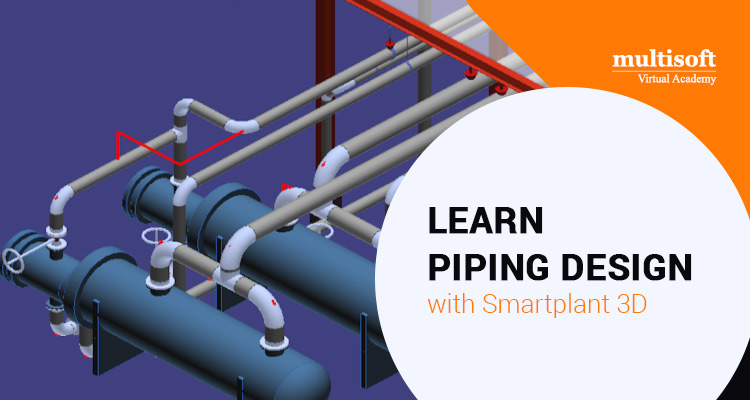
Advanced tools like SmartPlant, PDMS, Plant 3D, etc., allow you to build 3D models, perform clash checking, routing, and generate isometrics and bills of material.
8.3 Isometric Drawing Tools / Plugins
Plugins or specialized modules convert your 3D model into isometric diagrams, dimension them, and export to drafting. They automate tedious parts.
8.4 Best Practices in CAD Workflow
- Use layers appropriately (pipe, equipment, supports).
- Standard block libraries and symbol libraries.
- Template files with title block, legends.
- Naming conventions for layers and line numbers.
- Maintain version control & backups.
8.5 Common Pitfalls & Tips
- Don’t overcrowd annotations
- Use consistent units
- Keep tolerances visible
- Cross-check spec sheets vs actual drawing
- Maintain clarity and readability for site teams
9. Step-by-Step Process: From Concept to Construction
Here’s a sample workflow you might follow (or learn during Piping Design and Drafting Course):
9.1 Process Flow & PFD (Process Flow Diagram)
Start with high-level flow of your system: arrows, equipment, stream numbers. This tells you what lines you will need.
9.2 Creation of P&IDs
Translate the PFD into P&IDs by adding valves, instrumentation, control loops, line numbers, pipe specs.
9.3 Preliminary Layout & Routing
Place equipment in plot plan. Route major pipes in conceptual fashion to see possible interference or spacing issues.
9.4 Stress & Flexibility Analysis
Use software or hand calculations to analyze thermal expansion, stresses, ensure your design is safe in temperature cycles.
9.5 Detailed Drawing & Isometrics
With routing decided, generate detailed orthographic and isometric drawings. Annotate with dimensions, fittings, welds, supports.
9.6 Shop Drawing & Fabrication
Break system into spools. Provide cutting lengths, weld details, fitups, material lists.
9.7 Installation, Inspection & Testing
During installation, track deviations and update as-built drawings. Perform hydrostatic tests or other inspections. Document results.
10. How Piping Design and Drafting Training Helps You
Let’s see how structured training accelerates your learning and makes your journey smoother.
10.1 Bridging Theory & Practice
A good training program helps translate academic concepts (codes, fluid flow) into real drawings and decisions. Rather than reading alone, you do tasks under guidance.
10.2 Hands-on Projects & Real Case Studies
Training often includes sample projects—creating P&IDs, isometrics, routing, clash resolution. Real case studies help you see how plants are actually built.
10.3 Industry Tools & Standard Exposure
You get exposure to actual CAD software, standard symbol libraries, engineering codes. You become tool-ready when you join a job.
10.4 Portfolio Creation & Confidence
You finish with drawings or small projects you can show to employers. That proves your capability beyond just a resume.
10.5 Career Roles You Can Target
After training, you can explore roles like:
- Piping Designer
- Piping Drafter / Draftsman
- Piping Engineer (entry)
- CAD Technician for pipelines
- Freelance piping consultant
Training gives you a clearer roadmap.
11. Challenges Beginners Face & How to Overcome
11.1 Learning Codes & Standards
Codes like ASME B31.3 are dense and technical. Start with simplified interpretations; use worked examples. Over time refer to the standard for edge cases.
11.2 Visualizing 3D Routing in 2D
Many beginners struggle to mentally visualize how pipe goes in space. To overcome:
- Sketch in isometric or use 3D CAD early
- Use block models of equipment
- Practice turning orthographic views into 3D mentally
11.3 Clash Detection & Coordination
Clashes with structure, other systems (electrical, HVAC) are inevitable. Use 3D software, clash check often, and coordinate with other disciplines.
11.4 Revision Management & Change Handling
Design seldom stays the same. Keep disciplined version control, change logs, and cross-check revision drawings. Annotate changes clearly.
11.5 Keeping Up with Evolving Technologies
The field evolves — AI in diagram generation, digital twins, cloud CAD. Stay updated by reading, taking refresher courses, and participating in forums.
12. Tips to Accelerate Your Learning
Here are practical tips to push your progress faster:
12.1 Study Real Plant Drawings
Collect real P&IDs, isometrics, shop drawings. Reverse engineer them, understand their logic.
12.2 Visit Construction / Fabrication Sites
Seeing real pipes, flanges, field constraints helps you connect drawing to reality.
12.3 Use Books, Forums & Community
Books like Piping Drafting & Design (Parisher & Rhea) or Process Piping Drafting are classics. Forums like Eng-Tips share real issues.
12.4 Practice Mini Projects
Do small projects: design a pump piping, a heat exchanger loop, drain piping. This helps cement knowledge.
12.5 Stay Updated with Industry Trends
Read newsletters, follow software updates, study AI and automation in piping (see next section).
13. Future Trends in Piping Design & Drafting
The future is bright and evolving. Here are some emerging trends:
13.1 Automation & AI in P&ID Generation
Researchers are exploring automatic P&ID generation or correction using AI. One “transformer” model can translate a process flow diagram (PFD) into a P&ID. Similarly, rule-based autocorrection of P&IDs is being studied.
13.2 Digital Twin & Smart Pipelines
Digital twins (virtual replica of real pipelines) help simulate performance, detect faults, and optimize maintenance.
13.3 Augmented Reality for Field Validation
Using AR devices in the field, engineers and installers can overlay designs on existing piping to check alignment or clashes.
13.4 Cloud CAD & Collaborative Platforms
Cloud-based CAD and version control allow multiple designers to collaborate in real time, improving coordination and reducing duplication.
Because you begin with a strong foundation via Piping Design and Drafting, you are well positioned to adopt and ride these innovations.
14. Frequently Asked Questions (FAQ)
Q1: How long does a Piping Design and Drafting Training program usually take?
It varies with depth. Basic to intermediate programs may take 20–40 hours (e.g. 30 hours) Multisoft Virtual Academy. Advanced programs covering stress analysis, full plant modeling may take several months.
Q2: Do I need engineering background to learn piping drafting?
Not strictly, but a basic understanding of mechanical or civil engineering, fluid mechanics, or process flow helps. Many trainees come from engineering or drafting backgrounds.
Q3: Which software should I learn first?
Start with AutoCAD (2D drafting) then move to plant/3D tools like SmartPlant or Plant 3D. Also learn isometric modules or plugins.
Q4: Can piping drafting be freelanced or remote?
Yes — many firms outsource drafting or request remote CAD support. If you have a strong portfolio and software skills, freelancing is feasible.
Q5: What salary range can piping drafters/designers command?
It depends on region, experience, and complexity. In many countries, junior drafters earn moderate pay, while senior designers or engineers with piping skills command much higher. Because demand is niche, expertise pays.
Q6: How do I choose a good Piping Design and Drafting Training course?
Look for:
- Hands-on projects
- Use of industry tools & standards
- Instructor with real industry experience
- Course covering P&ID, isometric, routing, codes
- Portfolio outcome
Q7: Can I skip stress/flexibility analysis?
No — ignoring expansion or stress often leads to failures, leaks, or costly rework. Even if you outsource analysis, you need basic knowledge to design supports and routing safely.
Q8: After training, what role should I aim for first?
Start as a piping drafter / CAD designer under supervision. Over time, you may move to piping designer / engineer roles.
15. Conclusion
Piping design and drafting may seem like a labyrinth when you're new. But once you break down the journey into core concepts, learn your components, understand codes, and practice drawing, it becomes manageable — even enjoyable. A disciplined approach, hands-on training, and exposure to real projects will turn you from a beginner into a confident piping professional.
If you enroll in a structured Piping Design and Drafting Online Training program, you’ll gain guided practice, tool exposure, and standardized knowledge that accelerates your learning curve dramatically. Pair that with self-driven projects, site visits, and continuous practice, and you’ll be ready to enter this niche yet highly valued field.




![How Microsoft Azure Data Engineer [DP-203] Prepares You for Big Data, Streaming & Analytics](https://www.multisoftvirtualacademy.com/images/new-img/article/article_images/how-microsoft-azure-data-engineer-dp-203-prepare-you-for-big-data-streaming-analytics.jpg)

























-tutorial-for-beginners.webp)









 Training Certification Course.jpg)

.jpg)


.jpg)
 Basic Training Certification Course Online.jpg)
.jpg)






























.jpg)


 with Best Azure Course Online.jpg)




















.png)



 Online training.png)






















 Join our Live Instructor-Led online classes delivered by industry experts